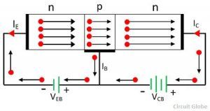
I CBO is the collector current with collector junction reverse biased and base open-circuited. What is ICBO and ICEO in a transistor what is relation between ICEO,ICBO and ICO? Typical n-p-n, p-n-p transistor junction voltages at 25 Deg C What are the values of collector to emitter, Base to emitter saturation, active, cut in, cut off voltages? What is the relation between α,β and γ in a transistor? γ is also called emitter injection ratio. In common collector configuration output is taken at emitter terminal, hence common collector current gain is given γ = I E / I B (input current is I B and output current is I E ). Alpha typically varies from 0.9 to 0.995.If we neglect reverse saturation current Ico then beta can be represented in terms of alpha, β= α / (1- α). α is large signal current gain of transistor in common base configuration α = ( I c – I co ) / ( I E -0).

Common emitter current gain beta (β) = Ic/I b as in common emitter configuration input current is I b and output current is Ic. Β is current gain of transistor in common emitter configuration. They are a) Common Base b) Common emitter c) Common collector configurations. What are the types of transistor configurations?īJT can be operated in three configurations with one terminal common to both input and output. As emitter is highly doped compared to collector it is advantageous to reverse bias collector base junction in order to have the advantage of high breakdown voltages. Also when you interchange the roles of emitter and collector with emitter base junction reverse biased then break down voltage decreases as break down voltage is inversely proportional to the amount of doping. Why inverse active mode of transistor is not useful?īipolar junction transistor internal design is in such a way that it will have high gain in normal active mode. Power dissipation across the transistor is given by Hence more voltage drop occurs across the collector junction. This is due to the fact that the collector junction is reverse biased, so offers more resistance to current flow. The power dissipation across the transistor mainly occurs at the collector junction. What is power dissipated by transistor in active region? Similarly PNP transistor is formed by sandwiching n-type semiconductor between two P type semiconductors. PNP transistor is formed by sandwiching n-type semiconductor between two P-type semiconductors. BJT is of two types 1) PNP transistor 2) NPN transistor. Transistor is active device which has the ability to control the electron flow through it. Emitter is heavily doped collector is moderately doped and base is lightly doped as we need most of the current from emitter should reach collector base current is needed only as a pilot signal for collector current variation. BJT has three terminals a) Emitter b) base c) collector analogous to cathode gate and anode in vacuum tube. The name Bipolar came from the fact that the device operation depends on movement of charge carriers with both polarities (holes and electrons). There are mainly three types of transistors used in electronic circuits they are a) bipolar junction transistor b) Junction field effect transistor c) Metal oxide semiconductor field effect transistor.

Transistor has three terminals and is used in electronic circuits as amplifiers and switches. Transistor is a semiconductor device capable of transferring the signal from high resistance to low resistance or vice versa.

It will tell what to expect from the component under a specified biasing condition, and are often (if not always) found in datasheets.What is a transistor and types of transistors? The curves you are talking about, are the representation of many quiescent points given by the variation of a parameter, which may be the value of a component, of a signal, or even an environmental parameter, such as the temperature. Its behavior is dynamic, as it will depend on the value of the two input voltages, but if these values are fixed, it's possible to determine the status of all the nodes and then eventually perform an analysis for small perturbations of this quiescent state. It's generally used in circuit analysis to find the operating region of active components, such as transistor and Op-Amps, and then perform a time-based analysis using the small-signal linear approximation of the component models. The quiescent point is by definition a state of a circuit in which all the inputs (meaning voltage and current levels, but also component values and environmental conditions) are fixed.


 0 kommentar(er)
